


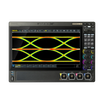


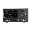


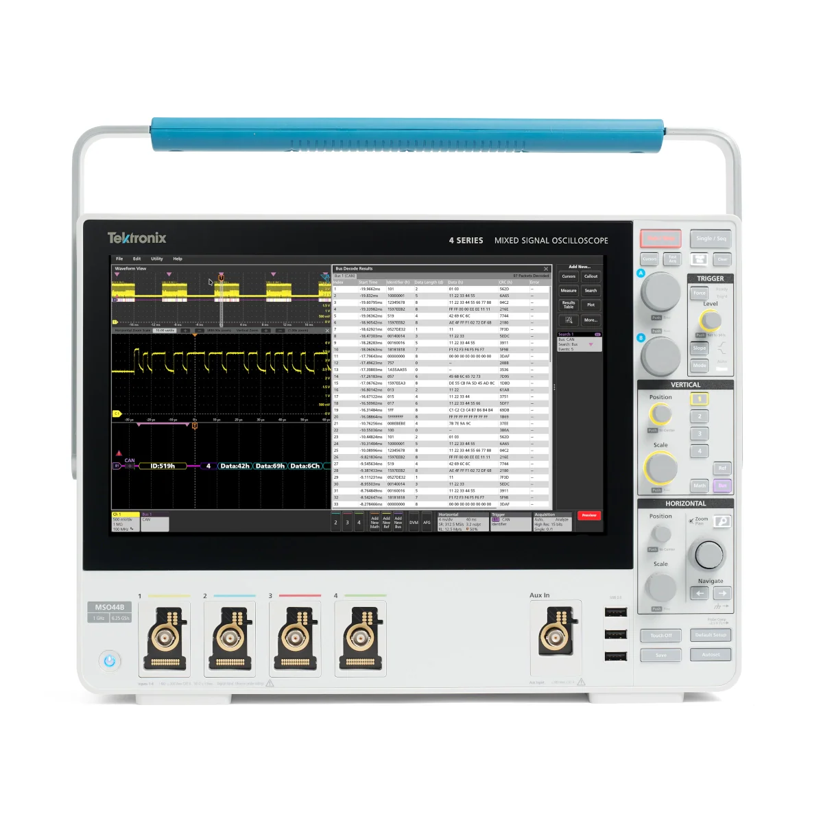
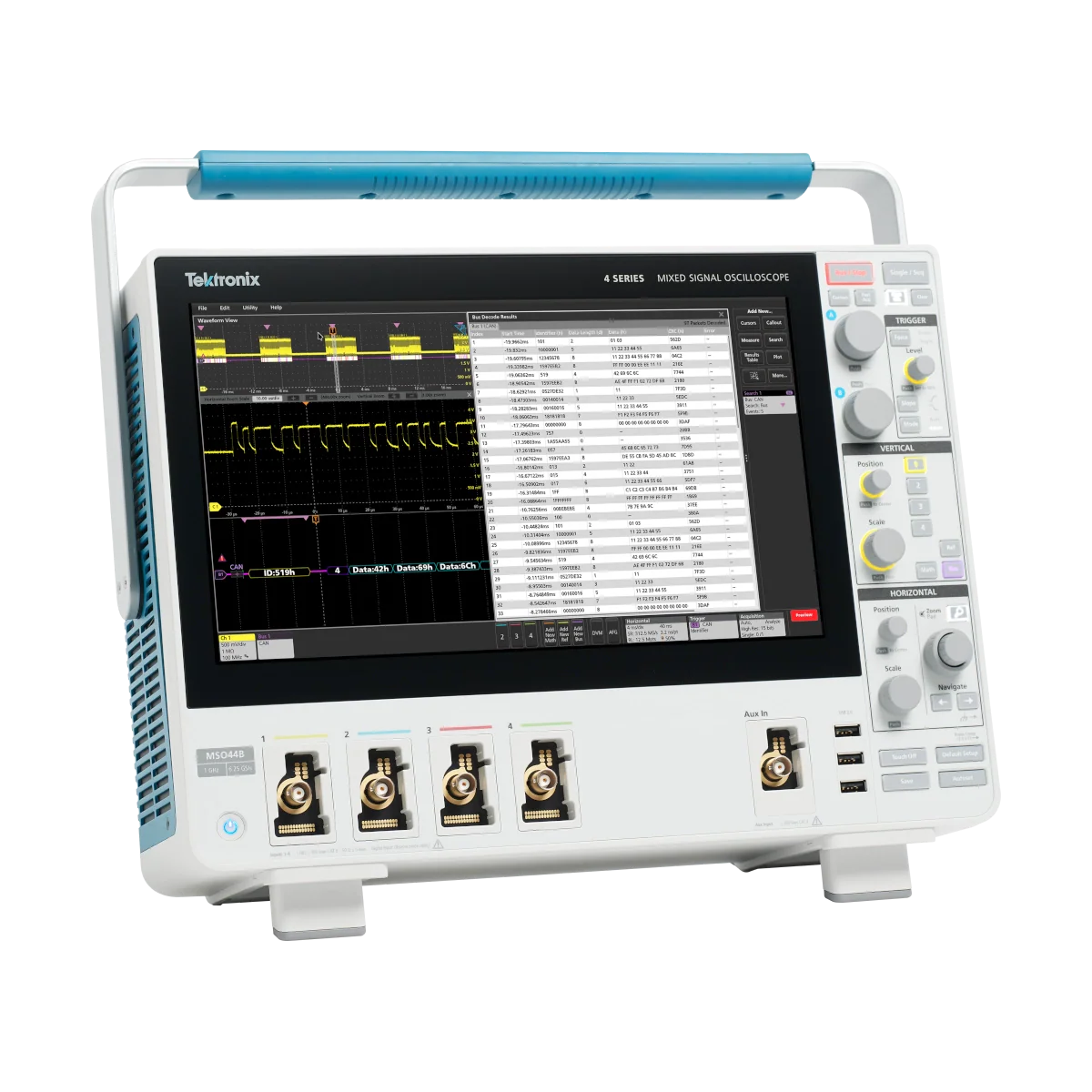
Tektronix MSO44B 1 GHz oscilloskop
Använd vår chatt för personlig support. Eller kontakta oss via +46 73-202 00 59 eller sales@GOmeasure.se
- Analog Bandbredd - 1 GHz
- Analoga Kanaler - 4
- Digitala Kanaler - Upp till 32 (Valfritt)
- Samplingfrekvens - 6.25 GS/s
- Inspelningslängd - 31.25 M till 62.5 M
%0ASamplingfrekvens%20-%206.25%20GS/s%0AInspelningsl%C3%A4ngd%20-%2031.25%20M%20till%2062.5%20M%0A%20
)
Upptäck möjligheterna
Mer information
Beskrivning
Vad är nytt i 4 -serien B
- Snabbare processor
- > 2x mer lyhörd användargränssnitt
- > 1,5x snabbare dataöverföringar
- Snabbare analys och seriell avkodning
- Ny skärm med större kontrast och visningsvinkel
- Två USB 3.1 värdportar
- Snabb e*Scope Browser-baserad fjärråtkomst
Big HD-skärm och prisbelönt användargränssnitt
Med samma användargränssnittsteknik som den prisbelönta 5-serien i ett kompakt paket, sätter 4 Series B MSO en ny förväntan på hur ett omfattning ska fungera.
- 13.3-tums högkontrast HD-skärm
- 6.1 tum (15,5 cm) djup bänkvänligt fotavtryck
Exakta mätningar och upp till 6 superflexibla kanaler
- Fin signaldetalj och exakta mätningar på alla kanaler
- 12-bitars vertikal upplösning (16-bitars i hög resläge)
- 6.25 gs/s på alla analoga och digitala kanaler
- Upp till 62,5 mpoints rekordlängd
- Varje kanal kan visa en vågform, RF -spektrum eller båda
- Alla ingångar kan användas för att se åtta digitala kanaler genom att ansluta en logisk sond
Enastående analys
- Upptäck den kapacitet som 4 -serien B kan ge till din bänk
- Ett brett utbud av smarta tekvpi -sonder
- Flerkanalspektrumanalys
- Upp till 48 digitala logikput
- Över 25 tillgängliga seriella protokoll
- Inbyggd godtycklig/funktionsgenerator
- AC/DC strömförsörjningsmätningar
- Automatiserad dubbelpulstestning
- 3-fas kraftanalys
- Fältuppgraderbara - Få de verktyg du behöver nu eller lägg till dem senare utan att behöva returnera instrumentet
För mer information: Tektronix
Dokument
Datablad:
Alternativ
Video
New 4 Series B MSO Oscilloscope Overview
This video provides an overview of the new 4 Series B MSO oscilloscope, highlighting the new faster processor, accurate and precise measurements, and the award-winning user interface.
4 Series B MSO - Outstanding Measurement Performance
The 4 Series B MSO offers powerful measurement and debugging tools. Watch this video to learn about visual triggers, segmented memory, 12 to 16-bit vertical resolution, automated measurements, plots, and statistical tools.
4 Series B MSO - Waveform Display and Controls
This video will give you a taste of the 4 Series B MSO's award-winning user interface, integrating an HD touchscreen display with traditional knobs and buttons. By the end of this video you will know how to use the 4 Series.
4 Series B MSO - Probes, Protocols, Spectrum Analysis, Power Analysis and More
The 4 Series B MSO is a versatile addition to your bench, addressing scores of signal types and applications. This video touches on available probes, RF spectrum analysis, mixed signal analysis, serial protocol decoding, signal generation, power supply measurements, and 3-phase power measurements.
Exploring the Integrated Arbitrary/Function Generator on an Oscilloscope
Having an arbitrary/function generator built into your oscilloscope is useful and convenient. Learn about the AFG outputs available in 2, 4, 5, and 6 Series MSOs.
Logic and Mixed Signal Analysis with a Tektronix Oscilloscope
Built-in logic analysis on mixed signal oscilloscopes expand visibility into digital systems. This video briefly overviews logic probe, settings, triggering, and searches.
Advanced Power Supply Measurements and Analysis with Tektronix Oscilloscopes
Learn how the Advanced Power Supply Measurements and Analysis package for Tektronix oscilloscopes simplifies analysis of power conversion systems with automated power quality, harmonics, switching loss, inductor, efficiency, and stability measurements.
Accurate Oscilloscope Measurement on 3-phase PWM Systems
Making measurements on the PWM (Pulse Width Modulation) outputs of inverters and motor drives is challenging. Learn about automated 3-phase power measurement packages on 4, 5, and 6 Series B MSO oscilloscopes that deliver consistent, accurate results.
CAN Bus Decoding and Triggering on an Oscilloscope
This video covers the basics of CAN bus decoding on Tektronix oscilloscopes as well as the setups for decoding, triggering, and searching for specific values or conditions.
I2C Bus Decoding and Triggering with an Oscilloscope
This video covers the basics of I2C bus decoding on Tektronix oscilloscopes as well as the setups for decoding, triggering, and searching for specific values or conditions.
SPI Bus Decoding and Triggering with an Oscilloscope
This video covers the basics of SPI bus decoding on Tektronix oscilloscopes as well as the setups for decoding, triggering, and searching for specific values or conditions.
Capturing a Clock Frequency Glitch with RF vs Time Trigger
See how an edge trigger on the RF Frequency Deviation vs Time trace isolates and captures a short duration transient in the frequency of a clock signal. The Spectrum View capability on the 4, 5 and 6 Series MSO oscilloscopes can perform edge, pulse width and time-out triggers on RF vs Time waveforms.
Triggering on an ASK (Amplitude Shift-Keying) Signal with Spectrum View
Watch this short demo of RF vs Time hardware trigger to see how an ASK (Amplitude Shift-Keying) signal changes over time. The Spectrum View capability on the 4, 5 and 6 Series MSO oscilloscopes can perform edge, pulse width and time-out triggers on RF vs Time waveforms.
Low amplitude RF emission analysis with RF vs Time Triggering
See how the RF vs Time hardware triggering capability (Spectrum View) on the 4, 5, and 6 Series MSO oscilloscopes can capture a low amplitude RF emission. This video focuses on the low amplitude RF emission from a car’s key fob using the Magnitude vs Time and Frequency vs Time triggers.
Spread Spectrum Clock Analysis with RF vs Time Triggering
See how to stabilize a hardware trigger on the up-down chirp pattern of a spread spectrum clock using a Frequency Deviation vs. Time trigger. The Spectrum View capability on the 4, 5 and 6 Series MSO oscilloscopes can perform edge, pulse width and time-out triggers on RF vs Time waveforms.
Finding Root Cause of EMI Signals with Spectrum View
See how to track down the source of transient RF/EMI emissions with Spectrum View and the RF vs Time triggering capabilities. Clearly determine which PCB signals are causing EMI emissions so that you can pass compliance testing quicker and easier. The Spectrum View capability on the 4, 5 and 6 Series MSO oscilloscopes can perform edge, pulse width and time-out triggers on RF vs Time waveforms.
Boosting the Waveform Update Rate Using Fast Acquisition Mode on the 4 Series MSO
See how different trigger types enable debugging of errant signals much faster and simpler.
Vad är nytt i 4 -serien B
- Snabbare processor
- > 2x mer lyhörd användargränssnitt
- > 1,5x snabbare dataöverföringar
- Snabbare analys och seriell avkodning
- Ny skärm med större kontrast och visningsvinkel
- Två USB 3.1 värdportar
- Snabb e*Scope Browser-baserad fjärråtkomst
Big HD-skärm och prisbelönt användargränssnitt
Med samma användargränssnittsteknik som den prisbelönta 5-serien i ett kompakt paket, sätter 4 Series B MSO en ny förväntan på hur ett omfattning ska fungera.
- 13.3-tums högkontrast HD-skärm
- 6.1 tum (15,5 cm) djup bänkvänligt fotavtryck
Exakta mätningar och upp till 6 superflexibla kanaler
- Fin signaldetalj och exakta mätningar på alla kanaler
- 12-bitars vertikal upplösning (16-bitars i hög resläge)
- 6.25 gs/s på alla analoga och digitala kanaler
- Upp till 62,5 mpoints rekordlängd
- Varje kanal kan visa en vågform, RF -spektrum eller båda
- Alla ingångar kan användas för att se åtta digitala kanaler genom att ansluta en logisk sond
Enastående analys
- Upptäck den kapacitet som 4 -serien B kan ge till din bänk
- Ett brett utbud av smarta tekvpi -sonder
- Flerkanalspektrumanalys
- Upp till 48 digitala logikput
- Över 25 tillgängliga seriella protokoll
- Inbyggd godtycklig/funktionsgenerator
- AC/DC strömförsörjningsmätningar
- Automatiserad dubbelpulstestning
- 3-fas kraftanalys
- Fältuppgraderbara - Få de verktyg du behöver nu eller lägg till dem senare utan att behöva returnera instrumentet
För mer information: Tektronix
Datablad:
New 4 Series B MSO Oscilloscope Overview
This video provides an overview of the new 4 Series B MSO oscilloscope, highlighting the new faster processor, accurate and precise measurements, and the award-winning user interface.
4 Series B MSO - Outstanding Measurement Performance
The 4 Series B MSO offers powerful measurement and debugging tools. Watch this video to learn about visual triggers, segmented memory, 12 to 16-bit vertical resolution, automated measurements, plots, and statistical tools.
4 Series B MSO - Waveform Display and Controls
This video will give you a taste of the 4 Series B MSO's award-winning user interface, integrating an HD touchscreen display with traditional knobs and buttons. By the end of this video you will know how to use the 4 Series.
4 Series B MSO - Probes, Protocols, Spectrum Analysis, Power Analysis and More
The 4 Series B MSO is a versatile addition to your bench, addressing scores of signal types and applications. This video touches on available probes, RF spectrum analysis, mixed signal analysis, serial protocol decoding, signal generation, power supply measurements, and 3-phase power measurements.
Exploring the Integrated Arbitrary/Function Generator on an Oscilloscope
Having an arbitrary/function generator built into your oscilloscope is useful and convenient. Learn about the AFG outputs available in 2, 4, 5, and 6 Series MSOs.
Logic and Mixed Signal Analysis with a Tektronix Oscilloscope
Built-in logic analysis on mixed signal oscilloscopes expand visibility into digital systems. This video briefly overviews logic probe, settings, triggering, and searches.
Advanced Power Supply Measurements and Analysis with Tektronix Oscilloscopes
Learn how the Advanced Power Supply Measurements and Analysis package for Tektronix oscilloscopes simplifies analysis of power conversion systems with automated power quality, harmonics, switching loss, inductor, efficiency, and stability measurements.
Accurate Oscilloscope Measurement on 3-phase PWM Systems
Making measurements on the PWM (Pulse Width Modulation) outputs of inverters and motor drives is challenging. Learn about automated 3-phase power measurement packages on 4, 5, and 6 Series B MSO oscilloscopes that deliver consistent, accurate results.
CAN Bus Decoding and Triggering on an Oscilloscope
This video covers the basics of CAN bus decoding on Tektronix oscilloscopes as well as the setups for decoding, triggering, and searching for specific values or conditions.
I2C Bus Decoding and Triggering with an Oscilloscope
This video covers the basics of I2C bus decoding on Tektronix oscilloscopes as well as the setups for decoding, triggering, and searching for specific values or conditions.
SPI Bus Decoding and Triggering with an Oscilloscope
This video covers the basics of SPI bus decoding on Tektronix oscilloscopes as well as the setups for decoding, triggering, and searching for specific values or conditions.
Capturing a Clock Frequency Glitch with RF vs Time Trigger
See how an edge trigger on the RF Frequency Deviation vs Time trace isolates and captures a short duration transient in the frequency of a clock signal. The Spectrum View capability on the 4, 5 and 6 Series MSO oscilloscopes can perform edge, pulse width and time-out triggers on RF vs Time waveforms.
Triggering on an ASK (Amplitude Shift-Keying) Signal with Spectrum View
Watch this short demo of RF vs Time hardware trigger to see how an ASK (Amplitude Shift-Keying) signal changes over time. The Spectrum View capability on the 4, 5 and 6 Series MSO oscilloscopes can perform edge, pulse width and time-out triggers on RF vs Time waveforms.
Low amplitude RF emission analysis with RF vs Time Triggering
See how the RF vs Time hardware triggering capability (Spectrum View) on the 4, 5, and 6 Series MSO oscilloscopes can capture a low amplitude RF emission. This video focuses on the low amplitude RF emission from a car’s key fob using the Magnitude vs Time and Frequency vs Time triggers.
Spread Spectrum Clock Analysis with RF vs Time Triggering
See how to stabilize a hardware trigger on the up-down chirp pattern of a spread spectrum clock using a Frequency Deviation vs. Time trigger. The Spectrum View capability on the 4, 5 and 6 Series MSO oscilloscopes can perform edge, pulse width and time-out triggers on RF vs Time waveforms.
Finding Root Cause of EMI Signals with Spectrum View
See how to track down the source of transient RF/EMI emissions with Spectrum View and the RF vs Time triggering capabilities. Clearly determine which PCB signals are causing EMI emissions so that you can pass compliance testing quicker and easier. The Spectrum View capability on the 4, 5 and 6 Series MSO oscilloscopes can perform edge, pulse width and time-out triggers on RF vs Time waveforms.
Boosting the Waveform Update Rate Using Fast Acquisition Mode on the 4 Series MSO
See how different trigger types enable debugging of errant signals much faster and simpler.